 OLED LCD Screen for Galaxy C8, C710F / DS, C7100 with Digitizer Full Assembly (Black)
 Subtotal: R767


Boards & Shields
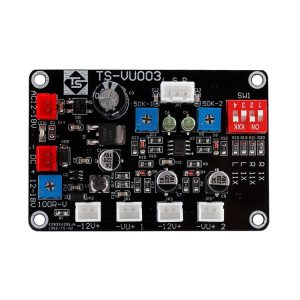
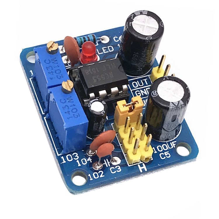
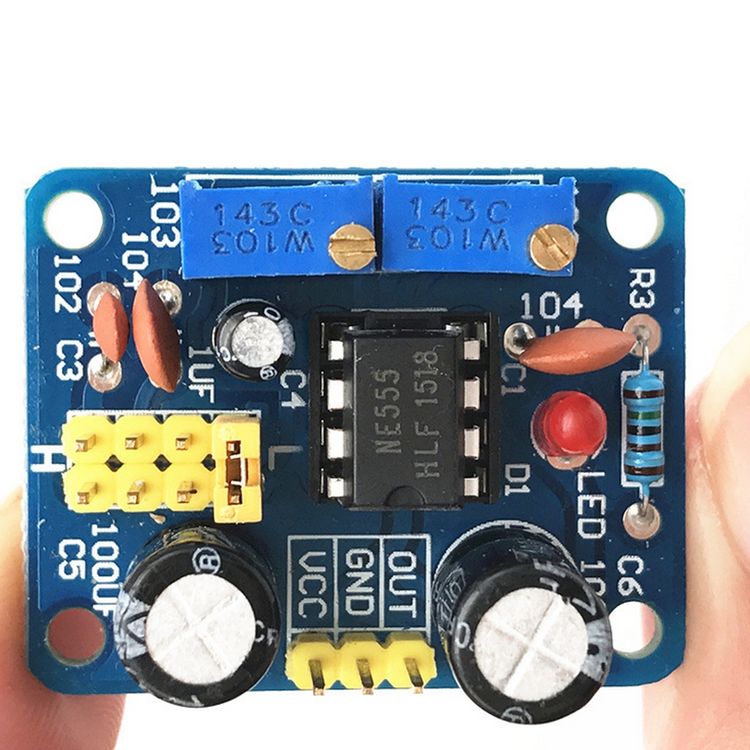
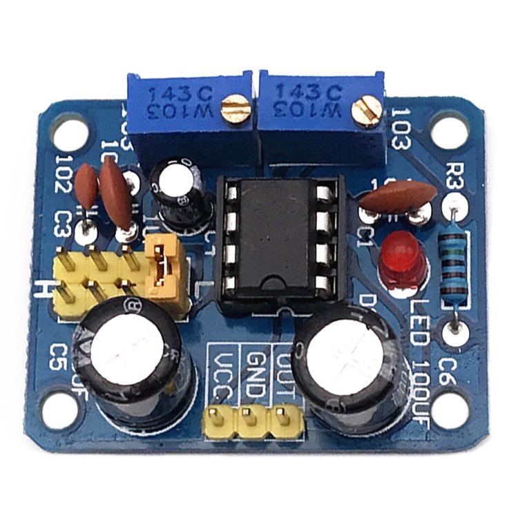
NE555 Pulse Module Board Frequency Duty Cycle Adjustable Square Wave Rectangular Wave Signal Generator
R49
In Stock at Supplier
Get 10% off your order by using the discount code YOINK10 at checkout!
| Didn't find what you're looking for? Take a look at these Similar Products | |
| Got questions or need assistance? Please take a look at our Frequently Asked Questions or Contact Us |
Overview
Scope of this module:
1. Used as a square wave signal generator to generate square wave signals for experimental development.
2. Used to generate a square wave signal that drives a stepper motor driver.
3. Generate adjustable pulses for use by the MCU.
4. Generate adjustable pulses to control related circuits.
Specification:
1. Size: 29x36mm, fixed hole distance 22.5×30.5mm
2. Main chip: NE555
3. Input voltage: 5V-15VDC. When 5V power supply, the output current can be around 15MA; when 12V power supply, the output current can be around 35MA;
4. Module weight: 10g;
5. Input current:> = 100MA
6. Output amplitude: 4.2V V-PP to 11.4V V-PP. (The output amplitude will be different according to the input voltage)
7. Output current:> = 15MA (5V power supply, V-PP greater than 50%), ≥35MA (12V power supply, V-PP greater than 50%)
Advantages
1. The output has LED indication, and it is clear whether there is output (LED quantity at low level, LED off at high level, LED flashes at low frequency)
2. The output frequency range can be selected (selected with a short-circuit cap) to make the output frequency more continuously adjustable;
– Low frequency range: 1Hz ~ 50Hz
– Intermediate frequency range: 50Hz ~ 1kHz
– Middle and high frequency range: 1KHz ~ 10kHz
– High frequency range: 10kHz ~ 200kHz
3. The output duty cycle can be fine-tuned, the duty cycle and frequency are not separately adjustable, adjusting the duty cycle will change the frequency; if you need a module with adjustable duty cycle and frequency,
4. The output frequency is adjustable;
– Period T = 0.7 (RA + 2RB) C
– RA and RB are adjustable from 0-10K;
– C = 0.001UF at low frequency;
– C = 0.1UF in the intermediate frequency range;
– Medium and high frequency gear C = 1UF;
– C = 100UF at high frequency, so the frequency buyer of the waveform can calculate it by himself.
Please save this page as an instruction, if you need a circuit diagram, you can ask the buyer after taking another picture.
1. Applicable occasions: MCU learning, electronic competition, product development, taxi meter, graduation design.
5. This product is not a precise circuit and is not suitable for use in places where high accuracy is required.
Additional Information
Weight & Size
Weight: 0.014kg
Size: 5cm x 5cm x 3cm
Delivery Options
We deliver straight to your home or office anywhere in South Africa.
- Courier Delivery with a cost of R75 on all orders.
Additional Charges
There are no extra fees or additional charges for shipping and delivering your order.
Processing, Handling & Delivery Timeframes
Once your order is placed, the following timelines apply:
- Order Cut-Off Time: 2:00PM (SAST)
- Handling Time: 1 – 2 business days (Monday – Friday)
- Transit Time: 5 – 7 business days (Monday – Friday) within South Africa.
- Total Delivery Time: 6 – 9 business days (Monday – Friday) within South Africa.
Note: Business days are Monday to Friday, excluding weekends and public holidays.
Kindly note that certain products may need extra time for processing and delivery, depending on where they are sourced from.
Shipping Locations
We only deliver within South Africa.
Shipping Carriers
We utilize the following couriers for order deliveries:
Order Tracking
Once your order is dispatched, you’ll receive an email with your delivery details and a tracking number. You can also track your order on our Track Your Order page.
Damages & Issues
Please inspect your order upon delivery. If you notice any damage, incorrect items, or missing products, check them in the presence of the courier and please Contact Us immediately. We’ll resolve the issue as quickly as possible.
Lost Orders
We guarantee the delivery of all orders. If your package is lost, stolen, or damaged, we will either send a replacement or issue a full refund.
Order Cancellations
You can cancel your order at any stage during the handling, shipping and delivery process. Please Contact Us if you need to cancel your order, and we’ll be happy to assist you.
Kindly Note: If the order has already been shipped, it must be returned or redirected back to the supplier before the order cancellation can be completed.
Order Modifications
You can modify or amend your order items before they are dispatched. Please Contact Us if you need to change anything on your order, and we’ll assist you.
Delivery Delays
While rare, delays can sometimes occur, particularly in remote areas. If your delivery takes longer than expected, please Contact Us, and we’ll assist you.
Failed Deliveries
If no one is available to receive your package at the delivery address, we’ll notify you of the failed attempt. We’ll then work to reschedule the delivery within 24-48 hours.
Changing Your Delivery Address
If you need to update your delivery address due to a mistake or change, simply reply to your order confirmation email with the correct details, or please Contact Us for assistance.
Overview
We offer a 365-days Return and Refund Policy, meaning you have 365 days from your date of purchase to request a return.
We want you to love your purchase! If you’re not completely satisfied, you can return the product for a repair, replacement, exchange, store credit, or refund.
Return Eligibility
To qualify for a return, your product must meet these conditions:
- Items must be in its original packaging.
- Items that was delivered defective, damaged, incorrect and missing parts due to errors not of your own.
- Items must be unused, undamaged, complete and not missing parts unless due to our error.
- Or used and/or unused items that are still within the warranty and guarantee period.
- You must provide proof of purchase.
How to Start a Return
To request a return, please Contact Us or submit a return request here or you can log a warranty claim request here. Once your return is approved, we’ll send you a return shipping label and instructions. Items returned without prior approval won’t be accepted.
Damages & Issues
Please inspect your order upon delivery. If you notice any damage, incorrect items, or missing products, check them in the presence of the courier and please Contact Us immediately. We’ll resolve the issue as quickly as possible.
Exchanges
To exchange an item, you’ll need to return the original product first. Once your return is approved, you can place a new order for the item you want.
Return Costs
All returns are free! We’ll arrange a courier to collect the item at no cost to you.
Restocking Fees
We do not charge restocking fees.
Lost Orders
We guarantee the delivery of all orders. If your package is lost, stolen, or damaged, we will either send a replacement or issue a full refund.
Order Cancellations
You can cancel your order at any stage during the handling, shipping and delivery process. Please Contact Us if you need to cancel your order, and we’ll be happy to assist you.
Kindly Note: If the order has already been shipped, it must be returned or redirected back to the supplier before the order cancellation can be completed.
Warranty and Guarantee
We want you to shop with confidence, which is why our products are covered by a 365 days Warranty and Guarantee.
All our products come with a minimum 365 days warranty and guarantee.
If you discover a defect within the first half of the warranty and guarantee period from the purchase date (as shown on your proof of purchase), we will gladly repair, replace, issue store credit, or provide a full refund.
For defects identified after the first half and within the second half of the warranty and guarantee period, we are happy to repair or replace the product.
You can log a warranty claim request here. Need assistance with a warranty claim? Contact Us for support and more details.
Additional Information:
All warranty claims go through an approval process handled by either Yoink and/or the manufacturer.
Please note that we do not cross-ship. This means we will only process returns once the defective product has been received, inspected, and approved for repair, replacement, store credit, or refund.
Warranty coverage will be void if:
- The product has been opened, tampered with, or altered.
- The serial number, manufacturer model, part number, or warranty sticker is missing, damaged, altered, or unreadable.
- The defect is due to wear and tear or physical damage.
- If a certified professional did not install it – (Depending on the nature of the product, eg. electronic components and/or repair parts).
For any further information, please Contact Us.
Refunds
Once we receive and inspect your return, we’ll notify you about the approval status. If approved, your refund will be processed to your original payment method within 10 business days. Please note that banks and credit card providers may take additional time to process the refund.
If more than 10 business days have passed since your refund was approved and you have not received your refund as of yet, please Contact Us.